Curved diamond crossings for the M&N RR - Part 1
The Mitchieburg and Natalieville RR has two crossings, neither of which has been laid yet. They are each curved and have been deliberately chosen in the planning stage to be non-standard to force some hand laying. Here is what the currently look like:
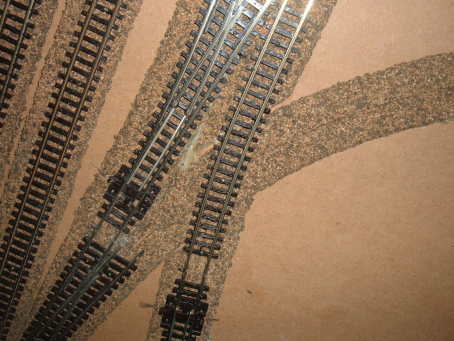
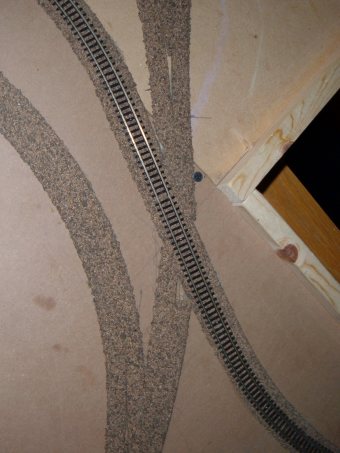
Both currently have flex track laid through one leg to get trains running. In both cases, this track will be removed and replaced with a crossing laid at the bench and additional hand laid track to connect at a convenient point to the existing flex track.
This little layout is all I have to run trains on at present so I’ll make first crossing the one near the turnout in the yard. That way I’ll have a little experience from building the first crossing before I mess with the main line.
Producing a drawing from digital photos
In order to lay the crossing, I need a drawing of the track. Both legs of this crossing are curved. I started by taking a series of digital pictures with the camera as parallel as possible to the sub roadbed. I tried a few settings, with and without flash for example as well as with and without macro. I picked the one that had the best focus, least amount of flare on the shiny bits and the minimum of distortion. The best shot was taken from about a foot away from the track.
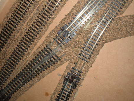
You can see the centerline on the roadbed on the right portion of the unlaid track and I will use the end of the diverging route of the right hand turnout on the left side to get good alignment of the sharper curve on the left-to-right leg. The shallower curve on the top-to-bottom leg has track in place so I can just match the drawing up to what has already been laid.
3rd Plan It to create a template for the crossing
There are many ways to turn the digital picture into a drawing of the crossing. The advantage of using 3rd Plan It is that it is geared to working with track and printing out drawings for track laying. (Other railroad design packages could probably be used too).
All I have to do is import the picture into 3PI, scale the drawing to the right size, put track sections on each of the legs then use 3PI’s connector tool to put curves in between. 3PI will also tell me what radius I have chosen. It’s then a simple matter to print out the track drawing without the ties and I have my crossing drawing mostly done!
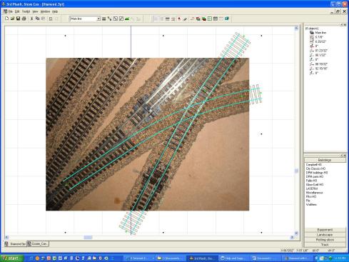
Here’s the picture imported in to 3rd Plan It with sections of track overlaid in a separate layer.
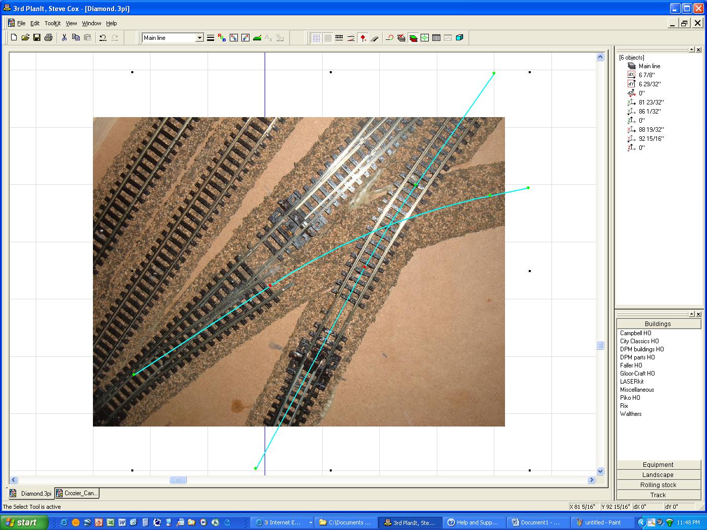
Here’s the same plan with the rails shown instead of centerlines and ties switched on:
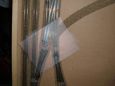
To double check scaling, I printed the drawing out 1:1 with the picture layer turned on. I cut out the drawing to eliminate any white areas of the printout and compared it to the actual track in place and was happy with the alignment. That’s a picture taped to the layout, not tracing paper!!! The sharper curve turned out to be 11” radius. For this small layout that is fine. The broader radius is 14 11/32”
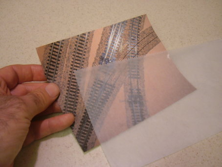
The next step is to set up a way to position PCB ties at the appropriate locations and solder rails in place. I placed the drawing in some waxed paper to get an idea of how this might be done.
Next Steps - Soldering rails to ties
I plan to use low tack, clear adhesive sheet to hold the ties in place. With the drawing under the adhesive sheet, I can clearly see the locations for the PCB and wood ties. I’ll use the 30 degree crossing template from Fast Tracks to guide tie placement and location of gaps since the custom one I’m making is very close to 30 degrees at the frog.
In Part 2 I’ll put some ties and rails in place and build the sucker! I’m jazzed! All up, the drawing was made in less than an hour. It took more time to write this post!
I hope you were able to make something for your railroad today too!
To Part 2…
 Steve Cox
Reader Comments (2)
I read with interest you article on N curved crossings. I am going to attempt to do one in HO code 70 myself. I don't have a computer capable of drawing the template like you do, so I will be following your progress to see if i can adapt it to HO. Pete.
Hi Pete,
Let me know how it goes. Send some pics!
Steve