Curved diamond crossings for the M&N RR - Part 3
This is a multi-part posting about hand laying an N Scale code 55 curved diamond crossing.
In Part 1: , I described making accurate drawings of the N Scale curved diamond crossing from digital photographs. Part 2 describes how I set up the ties for the diamond crossing using the drawings and putting the first few rails in place. This post focuses on setting the remaining rails in place.
In subsequent posts, I’ll secure the track assembly in place on the layout and wire the thing up for DCC. Painting and ballasting will come later.
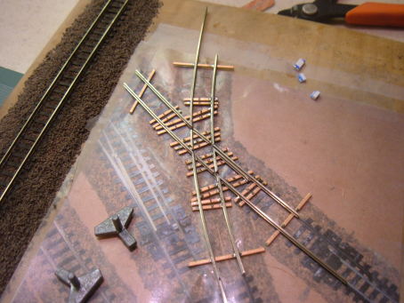
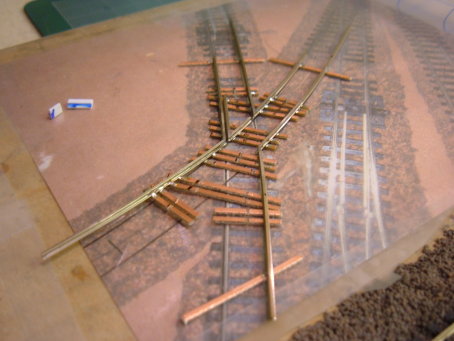
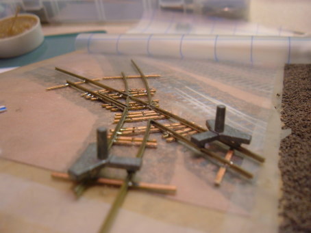
Here’s how far I got to tonight.
Guard rails & frog rails
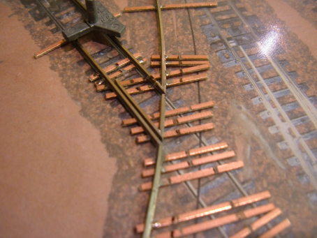
There are eight guard rails on the crossing not counting the inner diamond. Each of the guard rails connects with one of the frog rails at either a sharp point or a shallow angle. You can see in the photo below that a guard rail with the sharp connection has been made. I was tempted to just nick the base of the rail and bend a piece of rail for the joints that have shallow angles but instead, I decided to solder them up from two pieces of pre-curved rail. I did this for two reasons.
First, I wanted to pre-bend the rails to match the curves on each leg. And second, I expect that the lengths of the live rail between frogs will need to be adjusted (filed and or sanded) to get the correct spacing on the guard rails on both sides. That would be very difficult to do using the bending method.
Even though the frog rails will later be gapped, it is better to install them as a single piece rather than as two even smaller pieces of rail that both have to be individually shaped and aligned. Once soldered in place, the single pre-curved frog rail will stay in good alignment with itself when it is gapped later.
Guard rail spacers
Speaking of spacing for the guard rails, the correct spacing according to NMRA standard XRP-3 Proto-Fine Scale Track is 0.025”. I made some styrene spacers that are nominally 25 thou thick by laminating some 0.010” and 0.015” styrene strip. I put a small flange on one side to prevent the spacer dropping all the way down to the ties. That would be bad, as it is the rail heads that have to be 25 thou apart at the guard rails, not the rail bases. The flange just sits on the top of the rail head. The design isn’t the best but it will do for now and was quick to put together.
I used two small guard rail spacers while soldering in the first guard rail and frog rail assembly.
I decided do the rest of the frog rails like the loose end guard rail joint rather than pre-solder the guard and live rails ahead of time. That way I can align the frog rail and have it held in place as I fit and solder each guard rail. The key here is to make sure the ends of the live rail between the frogs is at the right flange way clearance distance on each side.
Shallow angle stock rails
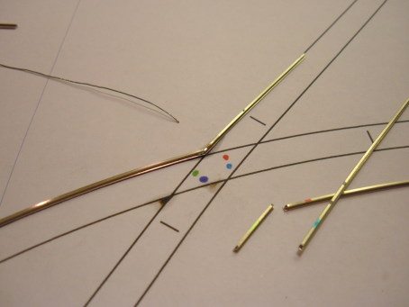
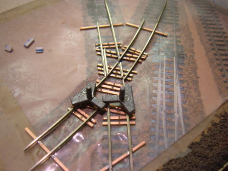
Working clockwise around the diamond, I cut the appropriate pre-curved stock rails and sanded bevels then soldered the two over the rails-only drawing in the photo below.
As the pre-curved pieces are cut and installed, you are left with smaller and smaller fragments of rail which could be confused with one another. I used magic markers in different colors (Target, $8 for 10 Sharpies in different colors) to mark each piece before it was cut. It is still possible to turn the frog rails end to end but a quick visual will tell you which way it goes in.
I then carefully set the pair in place on the crossing and held one leg (lower left to upper right in the photo below) with gauges while lining up the stock rails on the other leg. I then tacked the rail pair in place.
In retrospect, I should have used a piece of brass strip to align the leg through the crossing in the absence of the frog rail. I was able to align the ends by referring to the underlying drawing and sighting along the rail. With a curved rail I think you are better to use the brass strip method. In N Scale a few thousandths of an inch can be enough to cause poor operation.
I cut the second frog rail from the pre-curved stock and shaped the ends and test fit to get it’s length correct using guard rail spacers. With this frog rail tacked in place, I could check alignment of the full length rail on the other leg.
With everything looking line up, I carefully soldered the tacked frog rail in place. I’ll put the guard rails in later.
Sharp angle stock rails
Now I’m on a roll! I repeated the process with the remaining stock rails. In the photo above, I have already soldered the two rails together and tacked them in place. It was tricky to get both legs in gauge. As I slid one gauge along to check the spacing along one leg’s length, the rails would slide or pivot around the other gauge.
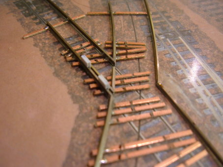
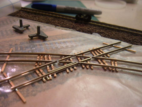
Here’s another view. Those may look like big gaps at the frogs but remember that the guard rails need to be laid in, and they’ll fill all but 25 thou of that gap.
Here the ends of the last stock rails are being soldered to the keeper ties.
I checked alignment by sighting and looking at the drawing under the crossing. The brass strip method would probably have been better. Here’s the view along the 11” curve.
And here’s the view along the 14 11/32” curve.
Almost at the point where I can run a car all the way over all frogs! With all stock rails now in place, the two remaining frog rails can be cut, shaped and test fit. With these frog rails, I used a track gauge while soldering to make sure gauge is maintained in the diamond itself.
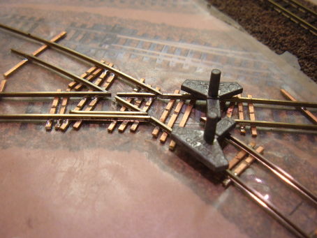
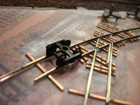
Here is a shot with one of the remaining frog rails in place. I can now run the trucks all the way through one leg! Yahoo! It’s still a little bumpy where the frogs are waiting for the guard rails as you might expect, but it’s a nice point to have reached.
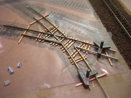
One frog rail to go. Had a little delay on this one. I was sanding the frog rail to shape when it caught the sanding disc and few out of my sight. I spent about ten minutes hunting around the kitchen for it! With the rail found again, I tacked it in place and checked the alignment before soldering it fully in place.
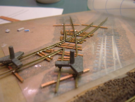
Excellent. Now it looks like a crossing! I carefully double checked alignment and gauge along all rails and then soldered everything in place that wasn’t already soldered, checking along the way to make sure nothing has moved.

And that brings me back to the first photo in this post. Rockin! The stock rails are done, the frog rails are in place and one guard rail is in place. Next on my list is installing the guard rails.
I hope you were able to make something for your layout too today!
To Part 2: Installing the ties for the diamond crossing using the drawings and putting the first few rails in place.
To Part 4: Installing the guard rails.
 Steve Cox
Reader Comments (4)
Nice blog, excellent pictures of your hand laid track, something I am just too timid to try.
Joe
Joe,
I felt that way too for a long time. Start out with a Fast Tracks jig and some quicksticks. It's easier than it looks and there's something very satisfying about making your own track.
The diamond is a little trickier without the jig but having made some turnouts, I was more comfortable taking the project on. Besides, no manufacturer is ever going to offer an 11" x 14 11/32" radius crossing!
- Steve
Terrific info - thanks.
But how do you WIRE it? I'm having an awful job finding sufficient info on wiring diamond crossings.
John - 071020-23:39EDT
John,
It's addressed partially in this post: Cutting gaps in the diamond. I have a few posts partially written and I hope to have this project fully documented in the next month or so including wiring in the reversing module. Stay tuned.
- Steve