A Question of Complexity - Part 3
This is the third in a series of posts about complex trackwork that prompted by a note from Hector, a blog reader in Brazil: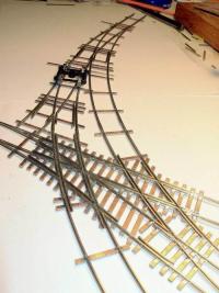
Can you tell me how to build this type of junction track?
I have a serious problem of space, and I want to build something like urban industrial tram track.
Part 1 considers the options of creating this type of track using commercial vs. handlaid track. Part 2 examines the origins of complex trackwork and considers examples of complex track.
This post will suggest factors that are important in creating successful complex trackwork in model form.
Simple Questions about Complex Track
When contemplating trackwork in confined settings, the following perspectives are worth considering:
- Can the prototype track plan be compressed into your available space?
- Will the modeled track lead to satisfying operations for you and your crew?
- Will the appearance of the trackwork be worth the effort once it’s done?
- Is the degree of difficulty of the trackwork within your track-laying ability
Taken together, the answers to these questions will tell you a lot about the challenges that lie ahead for layout planning and construction. Perhaps more importantly, the answers will also indicate if the end result will be a satisfying representation of your prototype, is interesting to operate and will run well. These are certainly good things to know before making the commitment to build.
If we take each factor one by one, we can tease out the beneficial factors and identify potential traps for modelers of complex track.
Compression
The key question here is “Can your prototype track plan be reduced into model form in your available modeling space?” The answer is almost always “not without making some changes!!” The world is inconveniently large. It’s always a challenge to convert even the smallest prototype rail lines into model form. And if your target space is small, it is even more challenging.
It is also worth thinking about scale at this point. If your available space is tight, N scale is a great way to go. N scale provides almost four times the railroad in the same space as HO. Or, the same HO scale layout can fit in a space a quarter the size if modeled in N scale.
One way or another, the prototype track arrangement needs to be reduced down so that the scaled version fits in our layout space. Through the miracle of compression and selective elimination of features, track planners usually manage to get a lot of the good stuff into their model plans. Compression is about shrinking prototype distances, sometimes dramatically so. Elimination is about removing features that just wont fit.
As an example, the switching lead along 2nd Street in Berkeley extends from Gilman Street to University Avenue, a distance of about 4000 feet or 3/4 of a mile. It parallels the UP Martinez Sub main tracks 300 feet to the east. Trackage in the area could fit within a scale rectangle 3/4 of a scale mile long and a little wider than 300 scale feet.
You can zoom in and drag this satellite view to explore the area.
In N scale, this rectangle translates to just under 25 feet in length (3/4mile x 33 feet/N scale mile = 24.75 feet). The 2nd Street lead is about 300 feet from the UP Martinez Sub main tracks, or 22.5 inches (300 feet x 12 inches/foot /160 = 22.5 inches). We’d need to allow a little room on the outside of the UP main and the 2nd Street lead. Let’s put six inches on the outside of each and you get pretty close to three feet wide (22.5 + 6 + 6 = ~36 inches).
The whole lead and adjacent main would be 25 feet long x 3 feet wide if faithfully reduced from full size to N scale. Not exactly a small layout!
Fortunately, faithful scaling of the real estate involved is not really the end goal or a good measure of success in layout planning. By compressing actual distances and omitting the non-essential parts, the flavor of the prototype could be preserved while pairing down the scaled plan to a size more in keeping with a small space.
Without doing any detailed analysis, I am confident that the length could be compressed to twelve feet in length by cutting out sections of the prototype right of way that had no visual or operational benefit. Twelve feet is about half of the directly scaled length of the area of interest. The layout may even operate well at eight to ten feet in length. Does it really matter if there is a two block distance on the prototype between two spurs and that this gets compressed to a couple of car lengths between spurs on the layout? Aside from the loss of faithfully reducing the plan to scale, the layout would likely still operate well and look good.
The lead and main tracks could be spaced closer together and I would expect that they’d comfortably fit on a layout deck of eighteen to twenty-four inches in width with each running more or less adjacent to one edge.
The compressed layout plan would fit into a space 12 feet by 2 feet and could possibly be reduced to fit into a space 8 feet by 1.5 feet. Now we’re talking about a reasonable size for a shelf layout.
The plan could be further shrunk by eliminating industries and their spurs from the plan. This also has the effect of shortening the layout but this time at the expense of operation. If you can, get as much value from compressing the boring parts before you start tossing out industries. As a practical matter, the loss of one or two industry spots is probably okay when the starting number is, say, ten or more. If the starting number of spots is six or lower though, I’d suggest trying to keep the original number of spots somehow as the reduction in the number of spots would lead to a somewhat limited range of switching routines i.e. less interesting to operate, at least from my perspective.
That’s always the challenge, more space leads to operational possibilities, while less space puts pressure on potential operations. The track planner needs to be thoughtful when the target space is small so as to not end up with a layout that fits in the target space, but is an operational flop.
All of the above assumes that the objective is a layout with complex track that operates well rather than a diorama that serves as a static display. There is a limit to how much the original track plan can be compressed and trimmed. Continued compression of a plan will progressively kill off sources of operation one by one until, in the extreme, the last spur is eliminated and you are left with a static tangent track display as your layout!
Operation
If you’re rolling down the route of complex track, you’re facing an above average challenge from the track laying stand point. It’s a good idea to be really sure that the layout will operate in a pleasing way once you’re done.
Unless of course, your main interest is building the complex track. If that’s the case, then feel free to skip this section. But, if you do care about operating your layout once the complex track is done, some careful consideration of the following items will payoff down the road after the champagne corks have finished popping at the start of your operations phase.
- Switching leads long enough
- Coupling cars on curves
- Sidings long enough
- Runarounds long enough
- Enough car spots
During the planning stage, identify all of your switching leads and make sure they are long enough. Long enough means at least enough lead track on the trailing end (points) of each spur to hold hold the typical switching locomotive(s) and one car to be spotted PLUS one car pulled from the spur. Here’s an example:
Leads that are longer will mean the spur is switched more quickly. Shorter leads mean more moves while switching and longer operating sessions.
Complex track often results in sharp curves, especially on spurs. Coupling cars on curves can be tricky, especially for longer cars and those with body mounted couplers. Where possible, ensure that there is enough straight track to hold the spotted car as well as a car or locomotive that will be retrieving it. In N scale a good minimum is about eight to nine inches of straight track plus the connecting curve to the switch. Double that for HO. If the curves can’t be avoided at the place where cars will be coupled, then it is worth ensuring that full size hands can easily reach in to help couplers to link up.
Siding length will affect operation in other ways. Longer sidings will hold more cars. That means more cars to be both pulled and spotted, and more cars to be sorted in the train before switching and after as well.
It is best to have at least one runaround near complex track. It does not have to be part of the complex track. In fact, if the runaround is a little distant from the complex track, time will be consumed sorting cars at the runaround and in travel time to the complex track where the spurs are located. In practice, runaround tracks require a wider right of way to accommodate the two tracks and this was not always available at the place where cars needed to be run around, especially if the track is in the street.
The length of runaround will affect how quickly runaround moves can be accomplished. If the runaround siding only holds a few cars, it will take some repetitive moves to get your locomotive on the other end of longer cuts of cars. That can add operational interest, or in can be a pain, depending on how inadequate the siding is compared to the normal cut length, and how much you and your operators like juggling cars before and after switching the spurs.
Having plenty of car spots leads to variety in the operating session. More car spots can mean longer operating sessions, more switching assignments for your crews or more variation in switching tasks as not every industry needs to be switched every session. For me, as a solo operator, the threshold is about eight to ten spots. Lower than that and operations seem limited. Your mileage may vary, but it’s good to decide what you are looking for in terms of destinations before you build because it will likely be challenging or impossible to add more spurs to your layout after the layout construction is under way.
Appearance
I am of the view that beautiful trackwork is a key layout feature. The look of nicely done track sets the whole tone of the layout and the reverse it also true. If the track looks good and operates well, I am already smiling and having fun. The rest is gravy.
So if you’ve got it, flaunt it, especially if the complex track is a key feature of operations. It is worth checking that your masterpiece be readily seen from the places where operators will view the layout. So much the better if the trackwork can be seen from multiple angles.
Complex track can mean a lot of switch moves are made in a single area, so it is best if the operator doesn’t need to reach repeatedly to throw switches or deal with couplers. Locating the complexity near the frond of the deck not only makes it easier on your operators, it will make it more visible. It will also make it a lot easier to maintain and trouble-shoot in the highly unlikely event that you have track problems ;-).
Degree of Difficulty
With track laying, the degree of difficulty increases according to the number of:

- Segments of curved rail (need to get the curve correct, more challenging to maintain gauge)
- Joints where two rails need to neatly join (Need to get the length and end angles right)
- Rail sections under an inch long (hard to hold while sanding or filing)
- Moving parts, typically points (tips end up very fine and can break or damage easily)
I’ll use a simple points system to compare the complexity of building a turnout and a diamond crossing. Let’s give one complexity unit for each bullet point in the list above i.e. for each segment of curved rail count ‘1’.
For a simple turnout, the complexity numbers are low. Two curved rails (2 points), two rails join at the frog (2 points), even in N scale all rails are over an inch long (0 points) and there are only two point rails to worry about, so that’s six. (2+2+0+2 = 6).
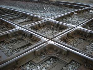
What a about a Diamond crossing? Let’s keep it simple and assume no curved rails. There are sixteen places (16 points) where rails come together at a solid joint in a diamond crossing. This is one of the reasons that the commercial outfits like to use plastic for frogs in diamond crossings - it dramatically cuts down on the number of joints to be created.
In N Scale, unless the crossing angle is very shallow, there are at eight rail pieces that are less than an inch long (the rails around the diamond and the live rails next to them - 8 points). The closer the angle of the crossing is to ninety degrees, the shorter the guard rails leading to the diamond (up to 8 points for short guard rails). We’ll call that sixteen points for short rails but you can see that it depends on the angle of the crossing.
The stock rails that lead in to the crossing could also be short depending on the place where the crossing will be located but this should not matter as those rails can be long during construction and trimmed to length on installation. There’s no moving parts so zero points for that one. Total points for a straight rail crossing: 0+16+16+0 = 32!
 A diamond crossing is all about cutting rails to length and shaping their ends to get the nice sharp joint. A score of about thirty-two for a standard crossing compared to six for the turnout shows pretty clearly which is more involved. I know which one I’d rather build! I think the score is a pretty fair reflection of the effort involved in building a crossing vs a turnout - about five times work to build a crossing compared to a turnout.
You can do the same scoring exercise for an N Scale crossing and an HO crossing The HO crossing will have a lower score (easier to build) as the rail pieces are generally longer.
When all the rails or even most of the rails are straight, trackwork is relatively easy. However, complex track often results in curved track segments in a crossing or turnout. This adds to the degree of difficulty as the rails need to have the correct curve and pairs of rails must stay in gauge for the track to operate smoothly once built. The tighter the curve, the more challenge involved. Gauge can be challenging to maintain within the length of a crossing or turnout when the radius is tight.
As a rule of thumb, I would prefer to not deal with curves under twelve inches in radius for handlaid crossings or turnouts in N Scale and fourteen inches would be a more comfortable minimum for radius.
Tracklaying skills
Handlaying track basically depends on shaping and cutting rail to the right length, with the right angle on the ends, then soldering those rail segments to gapped PCB ties. If you can do that, you can handlay track.
Handlaying is easy in N scale, and a lot easier in HO. I have heard a lot of modelers declare that they don’t have the skills to handlay. I’m sure they believe that but I am confident that lack of “skill” is not a permanent limitation. Skill largely results from four things:
- Desire
- Seeking out best practices
- Practice
- Learning from your mistakes
Of the four, desire is probably the most important. Desire is what drives us to create something in the first place and it operates on many levels: Desire for the ability or capability, desire for the feeling of accomplishment, desire for the end result. The list goes on. Desire drives us to find out how to do what we need to do to get what we want.
Usually, there are people out there who can save you a lot of grief by providing you the best methods and practices. The Fast Tracks website is a great resource and there links to other sites that are useful when handlaying in the links section of this blog.
Armed with some knowledge and some basic tools, you can launch into hand laying track, and no matter what, you’ll accomplish something. Whether the results are acceptable to you is up to you. And if your expectations aren’t met then you have a perfect opportunity to see what needs to be done better. Practice, learn, practice learn. By the third or forth time around, most people will be getting the hang of it. Start with switches and then move on to more complicated track elements like crossings.
The skills gained from laying switches and crossings is a great foundation for more complex trackwork. Rails still need to be trimmed and filed to length, soldered in place and wired up. With each successfully completed track component, the next seems a little less daunting. It is a great feeling knowing that even though atlas doesn’t make a #6 switch, you can hand lay one if you need to.
Accumulating skill is important. And you can be a lot more skillful with the right tools. Tools that I think are indispensable for handlaying track are as follows:
- 35W Soldering Iron with a fine tip
- Xuron Rail Nippers
- Fast Tracks Rail Roller for bending rail
- Fast Tracks Frog and Point Form tool
- Small benchtop belt sander
- Magnifier
- Basic digital electrical meter
- Jeweler’s Saw
- Track gauges
- NMRA gauge
- Flexible needle files
- Disposable nail files
Speaking of tools, a big boost to your track planning results is to use a turnout jig such as those made by Fast Tracks to build your turnouts. If you haven’t handlaid before, it will build your confidence and help you realize that anyone can handlay track. It will ensure that you develop your techniques for cutting, filing, soldering and gluing. Additionally, using a jig will ensure that you have all the tools you need for doing more freeform track components like a 46.5 degree crossing, a #4.75 turnout, a diamond crossing with curved routes or what ever else your track plan demands.
If you can, standardize your plan to use switches of just one or two sizes. Then there will be more turnouts of each size and it will be more economical to invest in a jig. A jig will save you time, money and effort as the parts for the same size switch will be the same and you can build them in small batches, choosing only the best parts for final assembly of your turnouts.
It’s So Simple, Really
Creating layout plans with complex track requires many of the same conceptual tools modelers have always relied on such as compression and selective elimination of less important plan elements. Care in planning will help the modeler understand the track laying challenges and will maximize the operational enjoyment of the layout once built.
There’s no doubt that well laid, smoothly operating complex track is a great feature for a layout. Although less and less common on the prototype these days, complex track is a great way to put a lot of action in a small space and can be a really good choice for a small layout.
Complex track inevitably depends on adequate hand laying skills. Complex trackwork is built up from turnouts and crossings, and skill can be developed in building these components individually prior to attempting complex arrangements. Tracklaying skill is a dynamic thing. Modelers can develop their skills quickly these days, with the benefits of good quality jigs available in all scales.
When it’s all said and done, if you have the right amount of desire, you can build complex track.
Thanks for the note Hector!
- Coxy
 Steve Cox
Reader Comments (1)
Wow! Two months without an update? Is everything alright? I always look forward to your posts. I hope to see some new posts soon.